Understanding the 400G DR4/DR4+ and FR4 Optical Transceivers

NADDOD Claire Optical Module Engineer Aug 3, 2023

In today's digital age, the demand for high-speed, high-bandwidth fiber optic transmission solutions in data center networks is growing rapidly. In this field, the 400G DR4/DR4+ and FR4 optical transceivers have attracted widespread attention. These transceivers not only provide impressive transmission speeds and bandwidth but also incorporate multiple innovative technologies for high performance and stability.


This blog will delve into the principles of the 400G DR4/DR4+ and FR4 optics, as well as their key technologies. By understanding these innovative technologies, we can better grasp the applications, advantages, and importance of these modules in data center networks to meet the ever-increasing data transmission needs.


Principle of 400G DR4/DR4+ & FR4 Transceivers

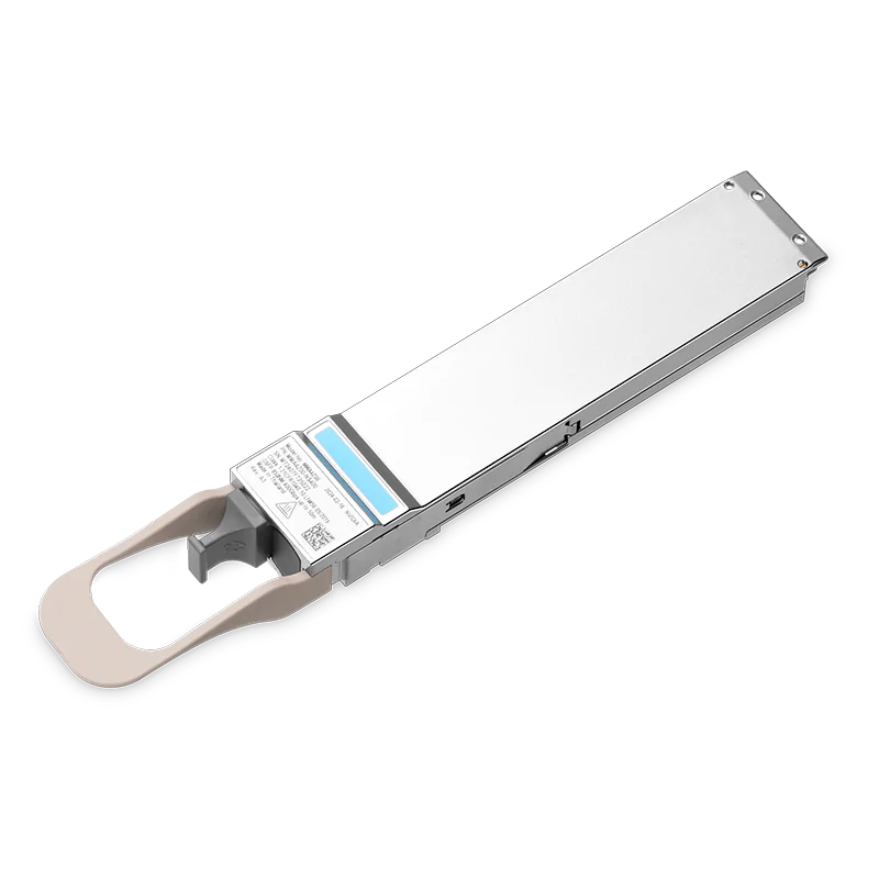
NADDOD's 400G DR4/DR4+ & FR4 optical transceivers comply with the IEEE 802.3bs & 802.3cu (Draft) standards and employ a platform-based hardware design. They can meet the transmission requirements of 500m and 2km, respectively.


The block diagram of the 400G DR4/DR4+ and 400G FR4 is shown below, with the 400G DR4/DR4+ transceiver using a standard 12-core MPO connector and the 400G FR4 transceiver using a standard dual LC connector.


The transceivers primarily consist of receiver and transmitter optical components, EML drivers, transimpedance amplifiers (TIA), PAM4 business chips (oDSP), controllers, and other components, totaling six parts.


In terms of transceiver design, NADDOD employs a complete range of independently developed key underlying components with proprietary intellectual property rights, covering end-to-end vertical integration solutions from optical chips (EML, PD) to electrical chips (driver, TIA, oDSP).


Schematic Diagram of 400G DR4/DR4+

Schematic diagram of 400G DR4 optical transceiver


Schematic Diagram of 400G FR4

Schematic diagram of 400G FR4 optical transceiver


The 400G DR4/DR4+ & FR4 optical transceivers utilize four optical channels, each carrying a 106.25Gbps signal, and eight electrical channels, each carrying a 53.125Gbps signal. Both optical and electrical signals employ PAM4 high-order modulation, and rate conversion is achieved internally through the transceiver's oDSP, which also handles clock recovery, signal amplification, and conditioning.


Additionally, the 400G DR4/DR4+ optical transceiver is designed for parallel transmission, with four channels using the same wavelength, while the 400G FR4 optical transceiver is designed for wavelength multiplexing, combining four channels with different wavelengths into one output through an optical multiplexer.


Compared to 100G CWDM4 and 100G PSM4, the 400G DR4/DR4+ & FR4 achieves higher system transmission rates by increasing the single-channel optical and electrical signal transmission rates and the number of electrical signal channels simultaneously.


Key Technologies

To meet the high-performance, low-cost, and deliverable requirements of 400G DR4/DR4+ & FR4 single-mode short-reach optical transceivers for data center applications, NADDOD has adopted several key technologies, including:


High-performance EML Lasers

The 400G DR4/DR4+ & FR4 modules utilize NADDOD's independently developed high-performance EML lasers. As shown in the diagram below, these lasers achieve high bandwidth and non-cooling application characteristics through optimized EAM quantum wells, DFB quantum wells, and grating designs.


The typical bandwidth exceeds 40GHz, and the transmitter TDECQ (transmit dispersion eye closure quaternary) performance optimization is greater than 0.5dB, reducing the demand for transmitter OMA optical power. This is beneficial for reducing system power consumption and improving long-term reliability.


Schematic Diagram of EML Structure

Schematic diagram of EML structure


Single-mode Lens PD Design

The 400G DR4 & FR4 optical transceivers utilize high-performance single-mode PD detectors with built-in lens design. These chips are assembled using Flip-Chip packaging technology and are optimized for special performance in conjunction with silicon photonic waveguide devices.


As shown in the diagram below, compared to traditional front-illuminated PDs, the single-mode lens PD employs a bottom-illuminated design with focusing characteristics, resulting in strong light-receiving capability and a 30% to 40% improvement in coupling tolerance. The use of Flip-Chip packaging technology also reduces the wire length from the PD to the TIA.


Schematic Diagram of Single-mode Lens PD Structure

Schematic diagram of single-mode lens PD structure

(Left) Traditional Front-Illuminated PD        (Right) Lens-Integrated PD


These features not only enhance the receiving performance of the transceiver but also lower the precision requirements for production processes, effectively ensuring the performance and cost competitiveness of NADDOD's optical transceivers.


Receiver Silicon-Photonics Hybrid Integration Design

NADDOD adopts silicon photonic waveguide devices (DeMUX) based on SiN material. Combined with the high-performance lens PD mentioned earlier, these devices are hybrid-integrated using Flip-Chip packaging technology to form the receiver optical component shown in the left image below.


Comparison of Silicon Photonic and Free Space Designs

Comparison of Silicon Photonics and Free Space Design

(Left) Free Space Design                    (Right) Silicon Photonic Integration


Compared to the Free Space design of optical components, as shown in the right image above, NADDOD's silicon photonic components reduce the number of optical elements by 60%. The passive assembly process is less complex, resulting in a 30% to 40% improvement in coupling efficiency. This achieves a transceiver solution with lower cost, better performance, and higher reliability.


Comparison between Silicon Photonic and Free Space Solutions

Type

Free Space Solution

Silicon Photonic Solution

Components

5

2

PD coupling process

Active coupling

Passive mounting

Cost

Medium

Low

Reliability

Higher

High


Chip-On-Board (COB) Packaging Design

For 400G DR4/DR4+ & FR4 transceivers, both the transmit and receive end optical chips (EML, PD) and electrical chips (Driver, TIA) are all integrated using COB packaging. This design involves chip placement and wire bonding processes to mount the chips on the PCBA board. The diagram below illustrates the system configuration of COB packaging for a 400G FR4 transceiver, with similar design structures for 400G DR4/DR4+ transceivers.
 

Schematic Diagram of COB Design

Schematic diagram of optical transceiver COB design


In this COB packaging design, the transmit end adopts a non-hermetic design, eliminating the substrate and hermetic enclosure used in traditional optoelectronic device packaging. This reduces material costs and simplifies the manufacturing process, facilitating automated production.


The receiving end utilizes the silicon photonic integrated optical components mentioned in the previous section, which have lower component complexity and improved coupling efficiency. The COB packaging mentioned above contributes to achieving high-performance, cost-effective transceiver solutions.


High-Performance oDSP

The 400G DR4/DR4+ & FR4 optical transceivers feature a self-developed 7nm 106Gbps PAM4 oDSP (optical Digital Signal Processor). This oDSP operates at an ultra-low core voltage, reducing chip power consumption. It incorporates a large-bandwidth multi-mode converter to enhance signal restoration quality.


Additionally, it supports a rich set of powerful digital algorithm equalizers. In addition to the common FFE (Feed-Forward Equalization) linear equalizer, it also deploys non-linear compensation algorithms at the transmit and receive ends to handle complex and diverse link impairments.


Furthermore, the oDSP provides extensive and powerful maintenance features, including SNR (Signal-to-Noise Ratio) monitoring, link transfer function estimation, and online firmware upgrade capabilities, enhancing network operational efficiency.


Others

In addition, the 400G DR4/DR4+ & FR4 optical transceivers also incorporate low-noise, high-bandwidth linear TIA (Transimpedance Amplifier) and high-bandwidth EML (Electro-absorption Modulated Laser) driver devices, meeting the data center's requirements for cost and power consumption.


Conclusion

In summary, the 400G DR4/DR4+ and FR4 optical transceivers represent the latest advancements in fiber optic transmission. As a leading provider of comprehensive optical network solutions, NADDOD has achieved higher bandwidth and faster transmission speeds in these optical transceivers through the use of high-performance lasers, innovative designs, and advanced signal processing technologies. This provides robust support for data center networks.


With ongoing technological advancements, we can expect these optical transceivers to play an even more significant role in future data center networks, driving progress and innovation in the digital age.


FAQ

1. What kind of patch cables should be used with QSFP-DD 400G DR4 and what kind of fiber should be used with QSFP-DD 400G FR4?

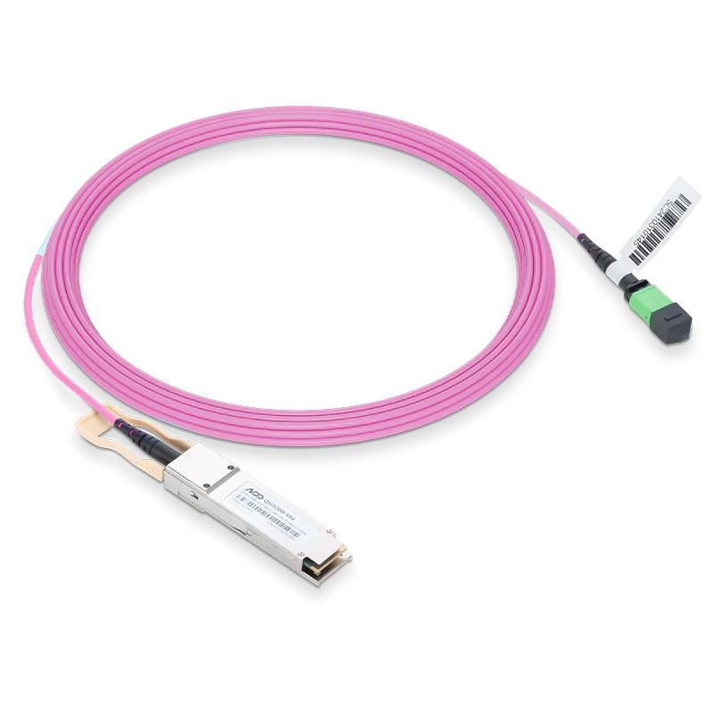
QSFP-DD 400G DR4 transceiver needs to be paired with a single-mode 12-core MPO interface and an APC connector, while QDD-400G-FR4 is a duplex LC interface, so it can be paired with a regular single-mode fiber with LC connector.


2. Does QSFP-DD400G DR4 support breakout connection?

QSFP-DD 400G DR4 module is an MPO interface, as long as the device port using the transceiver supports breakout function, then 400G DR4 can be interconnected with 100G DR transceiver with MPO to LC harness fiber. This scenario is very common in connecting 400G QDD switches to 100G QSFP28 switches.


3. QSFP56-DD has the standard 8*50G channel, why QSFP-DD 400G DR4 has only four channels?

The optical transceiver mainly completes the photoelectric conversion work, for its signal channel number, there are two dimensions: electrical signal (i.e., host side, connected to the device) and optical signal (i.e., the optical path side, connected to the fiber), 8 * 50G is its electrical signal channel mode on the host side, the QDD-400G-DR4 transceiver's DSP chip with the gearbox function, which can convert the electrical signal of 8X50G to 4X100G optical signal. The DSP chip of QDD-400G-DR4 transceiver has a gearbox function, which can convert 8X50G electrical signal into 4X100G optical signal.


4. What application scenarios are QSFP-DD 400G DR4 generally used in?

QDD-400G-DR4 transceiver is generally used in the interconnection of 400G leaf switch and spine, or interconnection of 400G QDD switch and 100G QSFP28 switch, with the increase of server NIC rate, it can also be used in the interconnection of 400G QDD switch and 400G OSFP/QSFP112 NIC.


5. Is the QSFP-DD 400G DR4 compatible with QSFP56 or QSFP28 ports?

No; QSFP-DD ports can use QSFP56 or QSFP28 optical transceivers, but QSFP-DD optical transceivers cannot be connected with QSFP56/QSFP28 ports.


6. What is the main difference between QSFP-DD 400G FR4 and DR4?

There are two main differences: First, the optical interface is different, DR4 is MPO interface, while FR4 is duplex LC interface, in the same transmission distance using FR4 is more saving fiber resources; Second, the transmission distance is different, FR4 detector sensitivity is higher, the theoretical transmission is 2km, while DR4 is only 500 meters.


7. Can QSFP-DD 400G FR4 be used in 200G QSFP-DD port?

No, the 200G QSFP-DD port is 8X25G mode and does not support PAM4, and the FR4 transceiver can't actively decelerate to 8X50G.