Advancing 400G Optical Transceivers in Metropolitan Converged Networks

NADDOD Nathan Optics Application Engineer Aug 10, 2023

As data centers and metropolitan networks continue to evolve, the demand for high-performance optical interconnect solutions becomes increasingly critical. The need for faster data transfer speeds, longer transmission distances, and efficient power consumption has led to advancements in coherent technology and optic module configurations.


In this blog entry, we will explore the requirements and challenges faced in data centers and metropolitan networks, and delve into the solutions that are driving the progress of optical interconnects, such as the emergence of high-performance LWDM transmitters and APD receivers. Join us as we uncover the latest developments in optical interconnect solutions and their impact on the future of data transmission.


Scenario Description


With the rapid development of 4K/VR videos and the Internet of Things (IoT), coupled with the diverse and new demands brought by 5G, such as ultra-high-definition videos, virtual reality (VR)/augmented reality (AR), IoT, and connected vehicles, the comprehensive backbone networks face various requirements, including ultra-high bandwidth, multiple connection channels, ultra-low latency, and high reliability.


Traditional 100GE interfaces in metropolitan area network (MAN) aggregation and core layers are no longer able to support the development of ultra-wide networks. Therefore, optical interconnect solutions based on 400GE have become an inevitable choice.


5G Backhaul Network Architecture

5G Backhaul Network Architecture


Taking the 5G service bearer network as an example, according to the bandwidth evaluation method by the Next Generation Mobile Networks (NGMN) Alliance, during the commercial deployment phase of 5G, the access layer bandwidth in the MAN evolves to 50GE, and the core layer bandwidth in the MAN evolves to 200GE/400GE.


5G Bearer Network Optical Module Bandwidth Requirements

Network Layers

MAN Access Layer

MAN Aggregation Layer

MAN Core Layer


5G Forward

5G Midhaul

5G Backhaul+DCI

5G Backhaul+DCI

Distance Requirement

<10/20km

<40km

40-80km

40-80km

Optical Transceiver

10/25G gray optics,

Nx25G WDM colored optics

25G/50G gray optics,

Nx25G/50Gb/s

WDM colored optics

100G/200G gray optics,

Nx100G

WDM colored optics

200G/400G gray optics,

Nx100G/200G/400G

WDM colored optics


Meanwhile, as data centers continue to extend from the core layer to the edge of metropolitan area networks and experience rapid growth in data center traffic, the demand for data center bandwidth has significantly increased. This has driven the rapid upgrade of business interface bandwidth for interconnecting data centers, with DCI interfaces transitioning from the current 100G to 400G.


DCI Network Topology Diagram

DCI Network Topology Diagram


Technical Trends


The scale of 5G infrastructure deployment is expected to be 1.5 to 2 times that of 4G, and the usage of optical modules in metropolitan area networks is estimated to reach tens of millions. The cost proportion of optical modules in the system continues to rise, making it crucial for operators to optimize the cost proportion of optical modules in network deployment investments.


Telecommunication customers also have an urgent need for 400GE optical modules that can achieve a 50% reduction in power consumption and cost per bit compared to 100GE optical modules. Additionally, telecommunication bearer networks have higher demands for reliability and performance compared to data center customers.


Optical Module Lifespan Requirements in Different Scenarios

Key Metrics

Telecom Operator

Data Center

Lifespan

Over 10 years

3 to 5 years


Furthermore, unlike data center networks with shorter transmission distances, metropolitan area comprehensive bearer scenarios have higher requirements for the transmission performance of optical modules.


Optical Module Transmission Distances in Different Scenarios

Scenario

Transmission Distance

DCN

100m~2km

Metropolitan Bearer

10~80km

DCI

80~120km


To achieve higher 400G transmission rates and reduce the cost per bit in metropolitan area comprehensive bearer scenarios, optical modules adopt similar technological approaches as in data center networking scenarios:


Increasing Optical Device Speed (Higher Baud Rate)

Improving the speed of optical devices is a highly effective way to increase line capacity, but it faces performance bottlenecks in III-V semiconductor laser devices. 25Gbps optical devices (DML, EML) for metropolitan area requirements have been widely adopted, while the 56Gbps optical devices are currently only available in the EML industry chain.


Increasing Channel Count (Multiple Lanes)

When the bandwidth and performance improvement of optical devices are limited, using multiple parallel channels, such as employing 4x25G NRZ technology for 100G transmission, can provide a high-capacity solution using existing mature industry chains to meet practical application needs in advance. In the era of 400G, multiple channel solutions are inevitable. Considering factors such as cost and power consumption, a suitable multi-channel architecture would be x4 or x8.


Adopting Higher-order Modulation

The advantage of using higher-order modulation formats is that it can improve spectral efficiency without increasing the signal's baud rate, thereby increasing the overall data transmission rate. Currently, the industry commonly adopts PAM4 modulation, based on 25G transmitters and receivers, to achieve a single-channel 50G transmission rate through PAM4 modulation, reducing the power consumption and cost per bit.


Additionally, due to the high requirements for reliability and performance in metropolitan comprehensive bearer optical modules, the industry has always maintained a high level of focus on technologies in these aspects.


More Reliable Devices

Optical modules for metropolitan comprehensive bearer applications are primarily used in telecommunications-grade scenarios, requiring a module lifespan of 10 years and the ability to operate within a temperature range of 0 to 70°C.


Therefore, telecommunications optical devices are sealed to ensure the reliability of module operation. In recent years, the low-cost demands of data center modules have driven the evolution of non-hermetic packaging technologies for optical devices.


However, applying non-hermetic technologies to telecommunications-grade scenarios still faces the following challenges:


LD (Laser Diode) Reliability

Non-hermetic packaging, due to its inability to provide complete sealing, imposes higher requirements on LD facet coating.


Condensation and Chemical Corrosion Risks of TEC (Thermo-Electric Cooler)

LWDM (Long Wavelength Division Multiplexing) devices use TEC for temperature control, which can cause localized temperatures of the device to be lower than the ambient temperature, posing condensation risks in non-hermetic environments. Prolonged exposure of TEC to moisture can lead to chemical corrosion risks.


Risk of Optical Path Contamination

Non-hermetic designs cannot completely prevent power fluctuations caused by condensation, contamination, and other factors from the LD chip to the optical receptacle. The absorption of moisture by adhesives inside the optical device can also result in relative positional changes of the optical path, leading to variations in output power.


High-Performance LWDM Transmitters

CWDM (Coarse Wavelength Division Multiplexing) has a wavelength spacing of 20nm and does not require TEC cooling, resulting in significant cost reduction. It can support applications up to 2km and is the mainstream solution for data centers.


LWDM (Long Wavelength Division Multiplexing), with a wavelength spacing of 5nm, offers lower dispersion and higher transmission performance compared to CWDM, making it the preferred solution for telecommunications metropolitan areas.


Taking the example of a 100G/lane solution, after transmitting over 10km, CWDM exhibits a much larger dispersion window compared to LWDM, with a dispersion penalty of 2.5dB for CWDM compared to 1dB for LWDM. In the era of 400G, CWDM cannot support long-distance transmission beyond 10km, making LWDM transmitters the mainstream solution for 400G in metropolitan comprehensive bearer networks.


High-Performance APD Receivers

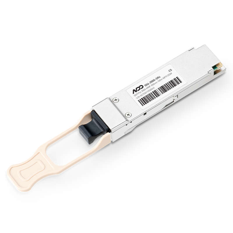
The transmit power of a 25G transmitter is typically between 0 and 3dBm, while the sensitivity of a 25G PIN receiver is generally <-7dBm, which does not meet the 40km transmission requirements of telecommunications optical modules. Long-distance transmission relies on high-performance APD (Avalanche PhotoDiode) receivers to enhance reception sensitivity.
 

Optical Module Optical Interface Specifications


Sensitivity Requirement

Receiver Type

Cost

400G LR8

-6.6dBm

PIN

Low

400G ER8

-16.1dBm

APD

High


Downward Trend of Coherent Technology

The 400G PAM4 solution is limited by device performance and cannot support long-distance transmissions beyond 80km. To achieve transmission distances of over 80km, mature coherent technology used in long-haul transmission networks needs to be introduced.


Additionally, the development of SiP (System-in-Package) and INP (InP-based) integration technologies, along with the continuous evolution of CMOS processes, supports the miniaturization and low-power evolution of coherent optical modules.


In the era of 400G, miniaturized ICT/ICR (Integrated Coherent Transmitter/Receiver) combined with low-power 7nm oDSP (optical Digital Signal Processor) enables the realization of 400GE miniaturized QSFP-DD coherent optical modules.


In 2017, the OIF (Optical Internetworking Forum) initiated the 400ZR project, defining interoperable CFEC (Consistent Forward Error Correction) and low-complexity 400G-16QAM modulation schemes, balancing performance and power consumption to support metropolitan 80-120km and DCI (Data Center Interconnect) applications.


Due to the advantages of low power consumption and small form factor, some customers also hope to use 400G ZR technology in urban edge access scenarios. However, the original performance defined for 400G ZR may not meet the requirements in these application scenarios.


Therefore, some optical module manufacturers have adopted algorithms with stronger performance and FEC (Forward Error Correction) algorithms based on the 400G ZR algorithm to meet application scenarios of 200-300km. The introduction of stronger performance also leads to increased power consumption, posing higher challenges for system heat dissipation. To address the heat dissipation issue, some manufacturers have chosen the CFP2 form factor for ZR+ scenarios.


Comparison of Different Transmission Distance Optical Modules

Optical Transceiver

Modulation Scheme

Optical Device Baud Rate

Subcarrier Count

Transmission Distance

Transceiver Packaging

Standard Compliance

400GE-LR8

PAM4

25Gbaud

8

10km

QSFP-DD

802.3bs

400GE-ER8

PAM4

25Gbaud

8

40km

QSFP-DD

802.3cn

400GE-LR4-6

PAM4

56Gbaud

4

6km

QSFP-DD

802.3cu

400G ZR

PDM-16QAM

61Gbaud

1

30km(w/o

EDFA)

QSFP-DD

OIF

400ZR

120km(w

EDFA

120km(w

EDFA

CFP2

/


Summary

In conclusion, the advancement of optical interconnect solutions is revolutionizing the way data centers and metropolitan networks operate. The adoption of high-performance LWDM transmitters and APD receivers is enabling higher data transfer speeds, longer transmission distances, and improved efficiency.


As the demand for faster and more reliable data transmission continues to grow, the industry is constantly innovating to meet these challenges. With the ongoing evolution of coherent technology, SiP and INP integration, and the introduction of standards like 400ZR, we can expect even more breakthroughs in optical interconnect solutions in the near future. The future of data centers and metropolitan networks is set to be faster, more efficient, and more reliable, thanks to the continuous advancements in optical interconnect technology.