Need Help?
sales@naddod.com
+(65) 6018 4212 Singapore
+1 (888) 998 7997 United States
+1 (855) 706 2447 Canada


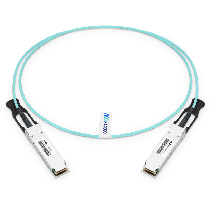
200G QSFP56 to QSFP56 AOC In Stock


200G QSFP56 AOC Hot


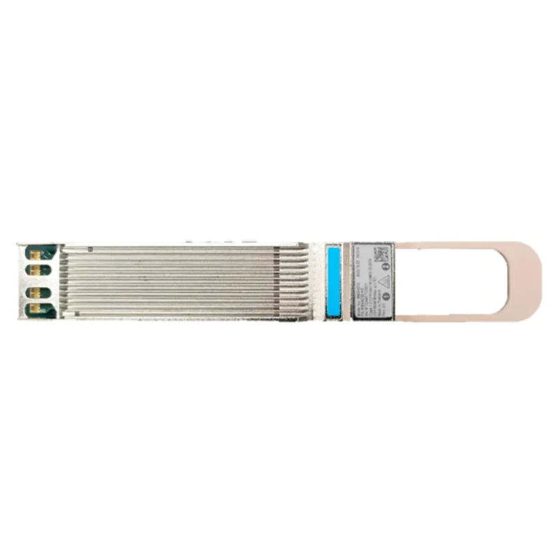
200G QSFP56 DAC Hot
Need Help?
sales@naddod.com
+(65) 6018 4212 Singapore
+1 (888) 998 7997 United States
+1 (855) 706 2447 Canada


